

For industries like aerospace, automotive, robotics, and manufacturing, Digital Twins are reshaping the way we design and validate systems. But Digital Twins are not just for large-scale industrial systems — they can also be implemented at a smaller, educational, and prototyping scale.
1. Introduction
The concept of the Digital Twin has quickly moved from buzzword to backbone in modern engineering. Put simply, a Digital Twin is a virtual replica of a physical system that interacts with its real counterpart in real time. It allows engineers to test, predict, and optimize performance without always touching the hardware.
In this article, we’ll build a Digital Twin of the TowerPro MG995 servo motor using:
- CATIA Dymola (for system-level simulation),
- Arduino Uno (for real-time control),
- and Arduino IDE (to program the microcontroller).
This hands-on Digital Twin combines the virtual model with the physical servo to demonstrate the power of simulation-driven engineering.
2. Why Digital Twin + Arduino + Dymola?
Let’s break down why this trio makes sense:
- Arduino Uno → affordable, open-source microcontroller, perfect for rapid prototyping.
- TowerPro MG995 Servo Motor → widely used, cheap, yet mechanically realistic for control testing.
- CATIA Dymola → a professional tool for modeling physical systems, based on Modelica language, capable of multi-domain simulation.
When you integrate these:
- The Arduino runs the control algorithm and commands the servo.
- The servo motor moves physically and provides feedback.
- Dymola simulates the servo’s dynamics in real time, comparing the physical vs virtual responses.
This setup is an example of Hardware-in-the-Loop (HIL) simulation, a cornerstone of Model-Based Systems Engineering (MBSE).
3. The Components
🔹 Hardware
- TowerPro MG995 Servo Motor
- 10 kg·cm torque at 6 V
- Operates with PWM (Pulse Width Modulation) signals
- 0°–180° rotation (approximate)
- Internal DC motor + gears + potentiometer feedback
- Arduino Uno
- ATmega328P microcontroller
- Generates PWM signals to control the servo
- Reads sensors if needed (e.g., potentiometer, encoder)
- Communicates with PC via USB serial
🔹 Software
- CATIA Dymola
- Graphical environment for building dynamic system models
- Uses Modelica for describing equations of motion, electrical behavior, and control systems
- Allows real-time co-simulation with external hardware
- Arduino IDE
- Programming environment for Arduino in C/C++
- Uploads control code (e.g., servo angle commands, PID loops)
- Handles serial communication with Dymola
📌 Workflow Summary:
- Dymola simulates the servo’s mathematical model.
- Arduino controls the real servo.
- Both systems exchange data for synchronization.
4. Understanding Servo Motor Modeling
Before jumping into simulation, let’s understand how a servo motor works.
A servo motor (like the MG995) is essentially:
- A DC motor → provides rotational torque.
- A gearbox → reduces speed, increases torque.
- A feedback potentiometer → measures position.
- A controller → compares commanded PWM signal with feedback and adjusts motor drive.
🔹 Mathematical Model
For a simplified model:
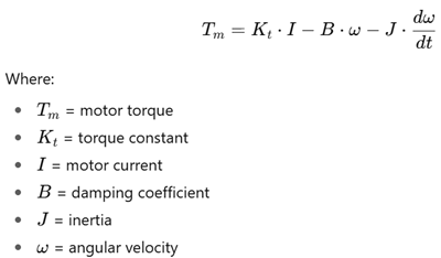
This model is implemented in Dymola with Modelica blocks.
5. Building the Servo Model in Dymola
Here’s how you’d create the virtual twin in CATIA Dymola:
- Open Dymola → Create a new Modelica class for the servo system.
- Import Modelica Standard Library → Provides components like DC motors, electrical sources, gears, inertia, etc.
- Assemble the servo model:
- DC motor block → input: voltage, output: torque.
- Gear block → converts torque-speed relationship.
- Rotational inertia block → represents load.
- Angle sensor block → feedback position.
- Set parameters (MG995 datasheet values: stall torque, no-load speed, supply voltage).
- Simulate step response (command 90° rotation).
- Observe outputs (position, velocity, torque).
At this stage, you have a pure virtual servo.
6. Programming Arduino for Servo Control
Now, let’s control the physical MG995 servo.
Example Arduino Code (PWM Control)
#include <Servo.h>

Servo myservo;
int angle = 0;

void setup() {
  myservo.attach(9); // Servo connected to pin 9
  Serial.begin(9600); // Serial comm with Dymola
}

void loop() {
  // Example: sweep servo from 0 to 180 degrees
  for(angle = 0; angle <= 180; angle += 10) {
    myservo.write(angle);
    Serial.println(angle); // Send angle to Dymola
    delay(500);
  }
}
- The servo sweeps angles, while Arduino sends angle data to the PC (Dymola) via serial.
- Dymola can compare this with the simulated servo’s response.
7. Interfacing Arduino with Dymola
Now comes the Digital Twin synchronization:
- Arduino → Serial USB → PC
- Arduino sends real servo angle data.
- Dymola receives it for comparison.
- PC → Dymola simulation
- Dymola computes simulated servo angle based on identical input.
- Both results are plotted together.
- Feedback Loop (optional)
- Dymola could send commands to Arduino.
- Arduino executes them, and servo responds.
This creates a two-way communication between physical and virtual models.
8. Control Strategies
Digital Twins become powerful when testing control algorithms.
🔹 Open-Loop Control
- Arduino sends fixed PWM signals.
- Servo moves — no feedback used.
🔹 Closed-Loop PID Control
- Arduino reads actual position (from potentiometer/encoder).
- PID loop adjusts PWM to minimize error.
Arduino PID Code Example:
// Pseudo-code for PID control
error = setpoint - measured_angle;
integral += error * dt;
derivative = (error - prev_error) / dt;

output = Kp*error + Ki*integral + Kd*derivative;
servo.write(output);

prev_error = error;
- Dymola runs the same PID simulation virtually.
- Comparison tells us if tuning is correct.
9. Real-Time Synchronization Challenges
Synchronizing Arduino + Dymola in real time isn’t trivial. Issues include:
- Latency: USB serial introduces small delays.
- Sampling rate: Arduino runs in ms, Dymola simulation uses step sizes.
- Non-linearities: friction, backlash in real motor not captured in simple model.
Solutions:
- Run Dymola at a fixed simulation step (e.g., 10 ms).
- Log real + virtual data for post-processing comparison.
10. Case Study: Digital Twin of MG995 Servo
Let’s walk through a concrete example:
- Virtual Setup in Dymola
- Servo model created with DC motor, gear, inertia.
- Input command: sinusoidal angle trajectory.
- Physical Setup with Arduino
- Arduino generates same sinusoidal command to servo.
- Reads actual angle via servo feedback.
- Comparison
- Dymola plots simulated angle.
- Arduino sends real angle via serial.
- Both curves are compared → differences show model inaccuracies.
- Result
- Simulated curve smoother, idealized.
- Real servo shows overshoot, deadband, noise.
This demonstrates how Digital Twins help in validating models against reality.
11. Applications
A Digital Twin of a servo might sound small, but the concept scales up to:
- Robotics → arm joints, grippers, humanoid movement.
- Drones → gimbal stabilization, flap actuation.
- Automotive → throttle/steering servos.
- Industry 4.0 → predictive maintenance using sensor-driven twins.
- Education → MBSE labs for mechatronics students.
12. Challenges and Best Practices
- Accuracy: Simple models may ignore friction, backlash, or temperature effects.
- Data handling: Serial comm speed limits real-time fidelity.
- Scaling: Works great for small demos, but large systems need powerful processors and fast comms.
Best practices:
- Start small (like this MG995 project).
- Validate your model step by step.
- Always compare simulated vs measured results.
13. Future of Digital Twins
The future points toward:
- Cloud Digital Twins → accessible from anywhere.
- AI-powered Twins → self-learning models that improve accuracy.
- IoT Integration → continuous data streaming from physical assets.
- 3DEXPERIENCE ecosystem → Dassault Systèmes already provides enterprise-scale Digital Twin solutions.
14. Conclusion
This project showed how to build a Digital Twin of a servo motor using CATIA Dymola and Arduino Uno.
- Dymola provides a virtual simulation environment for the MG995.
- Arduino executes the real control logic on the servo.
- The two are synchronized to validate control strategies.
By combining modeling, simulation, and physical prototyping, engineers can design safer, faster, and smarter — exactly what Digital Twins promise for Industry 4.0.
📊 Workflow Diagram
       +-------------------+         +------------------+
       |  CATIA Dymola     | <-----> |   Arduino Uno    |
       |  (Virtual Servo)  |         | (PWM Controller) |
       +-------------------+         +------------------+
                 |                             |
                 |                             |
        Simulated Angle                Physical Servo MG995
                 |                             |
                 +----------> Comparison <-----+