
Industrial equipment rarely fails without a reason.
A motor trips. A pump develops excessive vibration. A bearing overheats. An instrument begins drifting. A circuit breaker refuses to operate. A heat exchanger loses performance.
At the moment of failure, these events can appear sudden.
But in many cases, the final failure is only the last stage of a degradation process that may have been developing for hours, weeks, months, or even years.
The important reliability question is therefore not simply:
“What failed?”
It is:
“What physical mechanism caused the asset to lose its required function, and what conditions allowed that mechanism to develop?”
Understanding this distinction changes the way organizations approach maintenance.
Instead of repeatedly replacing failed components, teams can begin controlling the mechanisms that create the failures.
That is the foundation of effective reliability engineering.
Failure Is Usually a Process, Not an Event
When a bearing fails, the failure itself may occur in seconds.
But the mechanism behind the failure may have started much earlier.
Lubrication may have gradually deteriorated.
Contamination may have entered the bearing.
Misalignment may have increased mechanical loading.
Surface damage may have initiated microscopic fatigue cracks.
Temperature may have increased.
Vibration characteristics may have changed.
Eventually, the remaining load-carrying capacity becomes insufficient and the bearing can no longer perform its required function.
What operators see is the final event.
What reliability engineers need to understand is the entire degradation process.
A useful conceptual sequence is:
Stress → Degradation → Detectable Change → Functional Loss
The objective of reliability management is to intervene somewhere before the final stage.
The earlier the degradation can be understood and detected, the greater the opportunity to prevent failure or manage it in a controlled manner.
Failure Mode, Failure Mechanism, and Root Cause Are Not the Same Thing
These terms are often used interchangeably, but they describe different levels of the problem.
Consider an electric motor-driven pump.
The pump stops unexpectedly.
The functional failure is that the pumping system can no longer provide the required flow.
The failure mode might be:
Motor unable to run.
Further investigation finds that the motor winding insulation has broken down.
The failure mechanism is therefore electrical insulation deterioration followed by dielectric breakdown.
But why did the insulation deteriorate?
Perhaps the motor repeatedly operated above its thermal limit because the cooling passages were blocked.
The root cause might therefore be inadequate cooling caused by contamination combined with insufficient inspection.
The chain could be represented as:
Blocked cooling path
→ increased winding temperature
→ accelerated insulation degradation
→ insulation breakdown
→ motor trip
→ pump unavailable
Replacing the motor restores operation.
Cleaning the cooling system addresses the mechanism.
Improving inspection and controlling the operating environment addresses the root cause.
This distinction is important because replacing the failed component without addressing the mechanism often guarantees that the failure will eventually return.
ISO 14224:2016 provides a standardized structure for collecting equipment, failure, and maintenance data, including information concerning failure causes, consequences, mechanisms, and maintenance actions. This type of disciplined failure classification makes historical reliability data significantly more useful than a maintenance record containing only statements such as “motor damaged” or “bearing replaced.”
A Simple Model: Equipment Fails When Stress Exceeds Its Ability to Resist It
Almost every physical asset has some form of engineering margin.
A shaft can carry a certain mechanical load.
Insulation can withstand a certain electrical and thermal stress.
A bearing can tolerate a certain combination of speed, load, lubrication condition, and contamination.
A pipe wall can withstand a certain pressure while maintaining adequate thickness.
A sensor can operate within specified temperature, vibration, humidity, and electrical limits.
Failure becomes increasingly likely when either the applied stress increases or the asset’s ability to resist that stress decreases.
For example, a newly installed bearing may tolerate a certain operating load without difficulty.
Over time, poor lubrication can damage its surfaces.
Its effective condition deteriorates.
The external load may remain exactly the same, but the bearing’s ability to tolerate that load has decreased.
Eventually the same operating condition that was once acceptable becomes sufficient to cause failure.
This explains why saying:
“The equipment was operating normally when it failed”
can sometimes be misleading.
The operating load may have been normal.
The remaining strength of the asset may not have been.
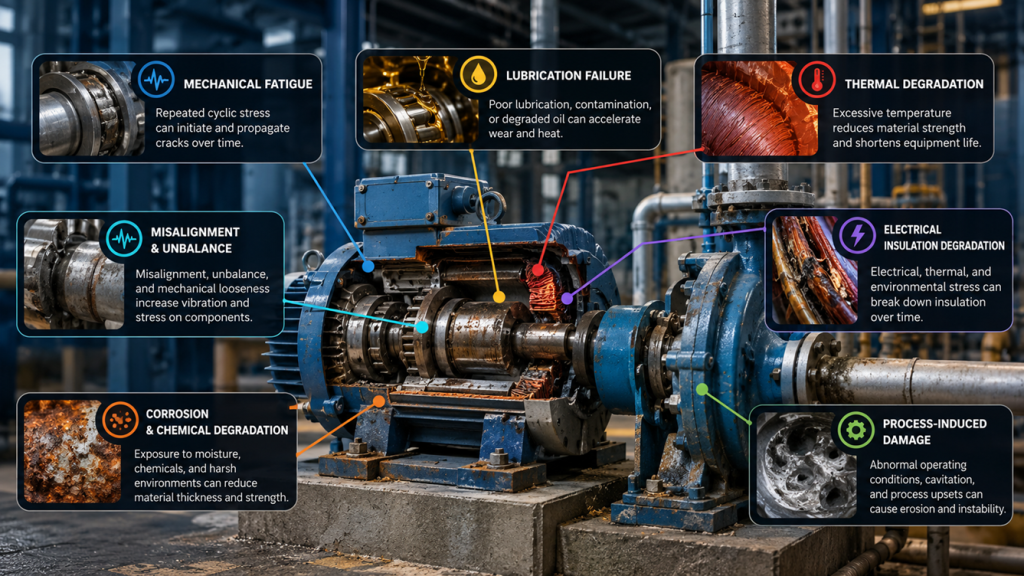
1. Mechanical Fatigue
Fatigue is one of the most important failure mechanisms in industrial equipment.
A component does not necessarily need to experience a single extreme overload to fail.
Repeated cyclic stresses below the material’s immediate breaking strength can gradually initiate and propagate cracks.
Rotating shafts, gears, bearing components, couplings, structural supports, bolts, and many other mechanical components experience cyclic loading during normal operation.
Each load cycle can contribute a small amount of accumulated damage.
Eventually a small crack may form at a stress concentration.
The crack grows with repeated cycles until the remaining section can no longer support the load.
Final fracture may then occur very quickly.
Common contributors include stress concentrations, sharp geometry transitions, poor surface condition, excessive vibration, misalignment, repeated start-stop operation, manufacturing defects, and loads higher than originally assumed.
This is one reason why repeated transient conditions matter.
A machine that starts and stops twenty times per day may experience a very different damage accumulation profile from another machine operating continuously at the same average load.
Understanding operating cycles can therefore be as important as knowing total operating hours.
2. Wear
Whenever surfaces move relative to each other, wear becomes possible.
Wear can gradually change clearances, surface geometry, friction, efficiency, and load distribution.
Different wear mechanisms can occur depending on the application.
Two surfaces may directly contact each other when lubrication is inadequate.
Hard particles may become trapped between moving surfaces and produce abrasive damage.
Repeated rolling contact can create surface fatigue.
Fluid containing particles can erode surfaces over time.
The important point is that wear is usually driven by operating conditions.
Replacing worn components without understanding those conditions may only reset the degradation clock.
For example, a mechanical seal may repeatedly fail.
The immediate maintenance response might be to replace the seal.
But the real mechanism might be dry running, shaft misalignment, excessive vibration, poor flush conditions, incorrect installation, or operation far from the pump’s intended operating region.
The seal is the component that fails.
The seal may not be the origin of the problem.
3. Lubrication Failure
Lubrication is often treated as a maintenance consumable.
From a reliability perspective, it is part of the machine’s load-carrying system.
A lubricant separates surfaces, reduces friction, removes heat, protects against corrosion, and in many applications carries contaminants toward filtration systems.
When the lubrication regime deteriorates, physical contact between surfaces increases.
Friction increases.
Temperature rises.
Wear accelerates.
Surface damage generates additional particles.
Those particles create more wear.
A self-reinforcing degradation cycle can develop:
Poor lubrication → friction → heat → surface damage → contamination → additional wear → failure
The lubricant itself may not necessarily be the original problem.
Lubrication-related failures can be associated with incorrect lubricant selection, insufficient quantity, excessive quantity, contamination, water ingress, degraded viscosity, clogged lubrication paths, poor storage practices, or inappropriate relubrication intervals.
Therefore a failed bearing should not automatically lead to the conclusion:
“Bearing quality problem.”
The correct question is:
“What lubrication condition did this bearing actually experience during its service life?”
4. Misalignment, Unbalance, and Mechanical Looseness
Many rotating machines continue operating with alignment or balance conditions that are less than ideal.
The immediate result may not be failure.
Instead, these conditions increase dynamic forces.
Those additional forces must be absorbed somewhere.
Bearings experience higher loading.
Couplings experience additional movement.
Seals experience increased shaft displacement.
Structural connections experience cyclic loading.
Vibration increases.
The secondary damage can eventually appear far away from the original problem.
This is why excessive vibration should not be treated as a failure mechanism by itself.
Vibration is often an observable response of the machine to an underlying mechanical condition.
The task is to understand the vibration pattern and determine what mechanism is likely generating it.
ISO 20816 provides guidance for measurement and evaluation of machine vibration, including consideration of both absolute vibration magnitude and changes from established operating conditions. ISO 20816-3:2022 specifically addresses many coupled industrial machines above 15 kW operating between 120 and 30,000 r/min.
A rising vibration trend can therefore be more informative than a single measurement.
A machine that historically operates steadily at 2.0 mm/s and rises to 4.0 mm/s may deserve investigation even if a generic alarm limit has not yet been exceeded.
The change contains information.
5. Thermal Degradation
Temperature is one of the most universal accelerators of equipment degradation.
Excessive temperature can affect lubricants, electrical insulation, seals, electronic components, batteries, cables, polymers, and mechanical clearances.
In electrical equipment, heat can be particularly destructive because insulation systems age over time.
Higher-than-intended operating temperatures can accelerate that ageing process.
In mechanical systems, excessive temperature may reduce lubricant viscosity, alter clearances, damage seals, or indicate abnormal friction.
In electrical connections, increased contact resistance can generate heat.
The heat can further degrade the connection.
Resistance increases again.
More heat is generated.
This creates another positive feedback loop:
Loose or degraded connection → higher resistance → heating → further degradation → more resistance → eventual failure
Infrared thermography is valuable in these applications because it can identify abnormal temperature patterns before the component reaches catastrophic failure.
But temperature itself is still only evidence.
The real objective is to determine why the heat is being generated.
6. Electrical Insulation Degradation
Electrical equipment depends heavily on insulation integrity.
Motors, generators, transformers, cables, switchgear, and other electrical assets operate because conductive components remain electrically isolated where required.
Insulation is affected by several stress mechanisms simultaneously.
Electrical stress, temperature, moisture, contamination, vibration, mechanical movement, chemical exposure, and transient overvoltage can all contribute to degradation.
The result may eventually include surface tracking, partial discharge activity, reduced dielectric strength, phase-to-phase faults, phase-to-ground faults, or complete insulation breakdown.
In medium- and high-voltage rotating machines, partial discharge measurement can provide useful information about insulation condition. IEC 60034-27-2:2023 establishes procedures for online partial-discharge measurements on stator winding insulation of certain rotating machines rated 3 kV and above.
The important reliability lesson is that insulation failure is rarely explained adequately by the statement:
“Motor winding burned.”
A stronger investigation asks:
Was the motor overloaded?
Was cooling sufficient?
Was contamination present?
Was the winding exposed to moisture?
Were there repetitive voltage stresses?
Was partial discharge developing?
Were connections deteriorating?
Was the machine operating outside its intended duty?
The burned winding is evidence of the final condition.
Reliability improvement depends on understanding what happened before it.
7. Corrosion and Chemical Degradation
Industrial assets frequently operate in environments where materials interact with water, oxygen, process chemicals, salts, gases, acids, or other contaminants.
Corrosion gradually removes material or changes its properties.
Pipe walls become thinner.
Electrical terminals oxidize.
Instrument tubing deteriorates.
Structural components lose section thickness.
Enclosures lose integrity.
Grounding systems deteriorate.
Corrosion can also interact with mechanical stress.
A small corrosion pit can become a local stress concentration from which fatigue cracking develops.
This interaction is important because real industrial failures often involve multiple mechanisms operating simultaneously.
Corrosion weakens the material.
Cyclic loading grows the crack.
Temperature accelerates chemical reactions.
Vibration increases mechanical stress.
The final failure may therefore be the result of several degradation processes rather than one isolated cause.
8. Process-Induced Damage
Sometimes the machine is mechanically healthy but is being operated in a process condition that continuously damages it.
Pumps provide a classic example.
A pump operating far from its intended hydraulic region may experience unstable flow, excessive recirculation, vibration, seal stress, bearing loading, and cavitation.
Cavitation occurs when local pressure conditions allow vapor bubbles to form and subsequently collapse.
Repeated bubble collapse near material surfaces can generate erosion and vibration.
The maintenance symptom may eventually be a damaged impeller or seal.
But repeatedly replacing those components will not solve the underlying process condition.
Similar mechanisms exist throughout industrial systems.
Valves can experience erosion from high-velocity flow.
Heat exchangers can suffer fouling.
Compressors can experience damaging operating conditions.
Piping can experience water hammer.
Filters can create excessive differential pressure when loaded.
Electrical motors can be overloaded because the driven process equipment requires more torque than expected.
Reliability engineering must therefore look beyond the equipment boundary.
Sometimes the mechanism that destroys an asset originates in the process.
9. Contamination and Environmental Exposure
Dust, water, chemicals, metallic particles, conductive contamination, and humidity can significantly change equipment reliability.
Contamination may enter bearings and lubrication systems.
Dust may block cooling paths.
Moisture may reduce electrical insulation resistance.
Conductive particles may accumulate inside electrical equipment.
Corrosive gases may attack contacts and electronics.
Instrument impulse lines may become plugged.
Outdoor enclosures may experience condensation.
The equipment may therefore be designed correctly and operated at the correct load but still fail because the surrounding environment was not adequately controlled.
This is why environmental data can be useful reliability information.
Ambient temperature, humidity, dust exposure, water ingress, enclosure condition, and ventilation performance may be relevant variables in understanding repeated failures.
10. Instrumentation and Control Failure Mechanisms
Instrumentation failures are often less visually dramatic than mechanical failures but can be equally disruptive.
Sensors may drift gradually.
Impulse lines may plug.
Transmitters may experience temperature effects.
Electrical connections may loosen.
Ground loops or electromagnetic interference may corrupt signals.
Control valves may experience stiction.
Positioners may lose calibration.
Communication systems may develop intermittent faults.
The equipment may still appear to operate, but the information supplied to the control system becomes inaccurate.
This creates a different class of reliability problem.
The physical asset may be healthy while the information representing the asset is wrong.
A drifting pressure transmitter, for example, can cause inappropriate control action.
A faulty temperature measurement can trigger unnecessary trips or fail to identify a genuinely dangerous condition.
For instrumentation, therefore, reliability must include both physical integrity and measurement integrity.
This is also why comparing redundant information sources can be valuable.
A process value that changes while all related variables remain unchanged deserves investigation.
11. Installation and Maintenance-Induced Failure
Not all degradation begins during normal operation.
Some failures are introduced before equipment is commissioned or during maintenance.
Examples include incorrect alignment, improper bolt torque, poor cable termination, contaminated lubrication during assembly, incorrect bearing installation, damaged seals, unsuitable replacement parts, inadequate cleaning, incorrect instrument configuration, or wiring errors.
The equipment may survive initial testing.
Failure appears later.
The time delay can make the connection between installation quality and failure difficult to recognize.
This is one reason post-maintenance verification matters.
Maintenance should not simply confirm:
“The equipment is running.”
It should confirm:
“The equipment has been restored to an acceptable condition.”
Depending on the asset, that verification could include vibration baseline measurements, thermal inspection, electrical testing, alignment verification, loop checking, operational testing, lubricant cleanliness, or other condition data.
Good maintenance restores function.
Excellent maintenance also avoids introducing the next failure.
Multiple Mechanisms Often Work Together
Real failures rarely fit perfectly into a single category.
Consider a motor-driven pump.
Slight misalignment increases bearing load.
Higher bearing load increases temperature.
The lubricant deteriorates faster.
Lubrication quality decreases.
Bearing wear increases.
Vibration rises.
The vibration worsens mechanical seal movement.
A small process leak develops.
Eventually the pump trips because vibration becomes excessive.
Which mechanism caused the failure?
The answer is:
the system of interacting mechanisms matters more than the final alarm.
This is why reliability investigations should resist the temptation to stop at the first plausible explanation.
“Bearing failure” is not enough.
“High vibration” is not enough.
“Overheating” is not enough.
Those statements describe what was observed.
The investigation should continue until the physical degradation process and the conditions enabling it are understood.
From Failure Mechanism to Detectable Signal
Every degradation mechanism produces consequences.
Some consequences can be measured.
Mechanical deterioration may change vibration.
Friction may increase temperature.
Electrical problems may change current, power, insulation characteristics, or partial-discharge activity.
Lubrication deterioration may change particle count, moisture content, viscosity, or wear debris.
Hydraulic problems may change pressure, flow, differential pressure, vibration, or acoustic characteristics.
Environmental degradation may correlate with temperature, humidity, or contamination.
The key principle of condition monitoring is therefore:
Measure the parameter that responds meaningfully to the failure mechanism you are trying to detect.
Installing sensors simply because they are available is not condition-based maintenance.
A useful monitoring system begins with an understanding of credible failure mechanisms.
ISO 17359:2018 provides general guidance for establishing machine condition-monitoring programmes and is applicable across machine types.
The engineering sequence should therefore be:
Asset Function → Functional Failure → Failure Mode → Failure Mechanism → Detectable Indicator → Monitoring Method → Maintenance Response
This approach prevents organizations from creating dashboards that contain large quantities of data but very little reliability value.
The P–F Interval: The Window Between Detection and Failure
Many failures provide some detectable indication before complete loss of function.
The point where a developing failure first becomes detectable is often called the potential failure point, or P.
The point where the equipment can no longer perform its required function is the functional failure point, or F.
The interval between them is extremely important.
Imagine a bearing.
Early-stage damage may initially become detectable through advanced vibration analysis.
Later, overall vibration rises.
Temperature begins increasing.
Noise becomes obvious.
Eventually the bearing fails.
Different inspection techniques therefore detect different stages of the same degradation process.
The objective is not necessarily to detect every failure at the earliest theoretically possible moment.
The objective is to create enough warning time to make a useful decision.
If detecting a degradation mechanism gives maintenance three weeks to plan work, prepare materials, coordinate production, and execute repairs during a scheduled shutdown, the monitoring system has created operational value.
If the alarm arrives thirty seconds before catastrophic failure, it may still provide protection.
But it provides very little maintenance planning value.
Why Time-Based Maintenance Does Not Prevent Every Failure
Traditional preventive maintenance assumes that performing maintenance at fixed intervals will reduce failure probability.
For some failure mechanisms, this works very well.
Components that experience predictable wear or age-related deterioration may benefit from scheduled replacement or overhaul.
But not every failure mechanism is strongly related to calendar age.
A new component can fail because it was incorrectly installed.
A recently maintained machine can fail because contamination entered during maintenance.
A cable can fail because of external damage.
A motor can fail because of an abnormal operating condition.
An instrument can fail due to moisture ingress.
This is why modern reliability strategies combine different maintenance approaches rather than relying exclusively on fixed intervals.
IEC 60300-3-11 provides guidance for developing failure-management policies using Reliability-Centred Maintenance techniques, while the current SAE JA1011 revision establishes evaluation criteria for RCM processes used to manage physical assets responsibly.
The maintenance policy should therefore match the failure behavior.
Some failures justify scheduled replacement.
Some justify condition monitoring.
Some require functional testing.
Some require redesign.
Some are best managed through operating procedures.
And some low-consequence failures may reasonably be allowed to run to failure.
Reliability engineering is about choosing the correct response—not simply performing more maintenance.
More Maintenance Does Not Automatically Mean More Reliability
This is an important point.
Maintenance itself introduces intervention.
Equipment is opened.
Connections are disturbed.
Components are removed.
Lubrication systems are exposed.
Settings may be changed.
Human error becomes possible.
Therefore unnecessary maintenance can sometimes introduce additional failure risk.
The objective is not:
maximum maintenance.
It is:
the right maintenance at the right time for the right failure mechanism.
This is one of the fundamental ideas behind Reliability-Centred Maintenance.
Failure Data Should Become Organizational Knowledge
One of the largest missed opportunities in industrial reliability is poor failure recording.
A work order might contain:
Pump repaired.
Or:
Motor bearing replaced.
This information is almost useless for long-term reliability analysis.
A stronger record might state:
Drive-end bearing replaced following increased vibration. Inspection found lubricant contamination and surface damage. Seal integrity was inadequate and moisture ingress was identified.
Now the organization can begin identifying patterns.
If similar failures repeatedly occur, the problem may no longer justify repeated corrective maintenance.
It may justify engineering improvement.
ISO 14224 emphasizes standardized collection of equipment, failure, and maintenance information precisely because consistent data enables meaningful reliability analysis across time, assets, facilities, manufacturers, and contractors.
Historical failure records should therefore answer more than:
What component was replaced?
They should help answer:
Why did we need to replace it?
From Reactive Maintenance to Failure-Mechanism Management
A reactive organization sees:
Bearing failed.
A preventive organization sees:
Replace the bearing every two years.
A condition-based organization sees:
Bearing vibration is increasing.
A reliability-focused organization asks:
What mechanism is degrading this bearing, what conditions are causing it, how can we detect it early, and can we eliminate or control the mechanism itself?
That final step is where major reliability improvement occurs.
Monitoring can identify degradation.
Maintenance can restore condition.
But engineering changes can sometimes prevent the degradation from recurring.
For example, repeated bearing failures may eventually be eliminated through alignment improvement, better sealing, lubricant contamination control, improved foundation stiffness, changes in operating practice, or equipment redesign.
The best failure is not necessarily the failure detected earliest.
It is the failure mechanism that has been eliminated where economically and technically justified.
Where Industrial IoT Fits
Industrial IoT becomes valuable when it extends visibility into degradation mechanisms.
A connected vibration sensor is valuable if it helps detect mechanical deterioration.
Temperature monitoring is valuable if it identifies abnormal thermal conditions.
Electrical monitoring is valuable if current, voltage, power, imbalance, demand, or operating cycles reveal abnormal asset behavior.
Environmental sensors are valuable if temperature, humidity, water ingress, or other conditions influence equipment reliability.
Process data is valuable when it helps distinguish machine problems from process-induced problems.
The objective is therefore not simply to put equipment online.
It is to create a continuous evidence stream that answers:
Is the asset behaving differently from normal?
Is the change significant?
What failure mechanism could explain it?
How quickly is the condition developing?
What action should be taken?
This is where condition monitoring evolves into decision support.
From Monitoring to Smart Insights
Traditional monitoring systems show measurements.
A more useful industrial intelligence system adds context.
Instead of:
Vibration = 4.6 mm/s
the system might say:
Drive-end vibration has increased 31% during the last seven days and is continuing upward.
Instead of:
Motor current = 84 A
it might say:
Motor current is 12% above the historical operating baseline for the same production condition.
Instead of:
Bearing temperature = 78°C
it might say:
Bearing temperature has increased 9°C while ambient temperature and load remain approximately unchanged.
That contextual information helps engineers decide what deserves investigation.
But algorithms should not automatically be treated as diagnosis.
A rising vibration trend does not automatically prove bearing damage.
Higher motor current does not automatically prove electrical deterioration.
Temperature increases can have multiple causes.
The purpose of smart monitoring is to reduce the search space, helping engineers identify abnormal behavior faster and direct their attention toward credible failure mechanisms.
Engineering judgement remains essential.
Reliability Is Ultimately About Managing Risk and Value
Not every failure deserves the same level of attention.
A small non-critical fan and a compressor that can shut down an entire plant should not receive identical reliability strategies.
Failure consequences matter.
Safety consequences matter.
Environmental consequences matter.
Production consequences matter.
Repair cost matters.
Redundancy matters.
Detectability matters.
ISO 55000 and ISO 55001 place asset management within the broader objective of realizing value from assets while managing performance, risk, and expenditure throughout their lifecycle. The 2024 revision of ISO 55001 explicitly strengthens the connection between asset-management decision-making and value.
This provides the wider business context for reliability engineering.
The objective is not zero failures at any cost.
The objective is to manage equipment so that the organization achieves the required performance at an acceptable level of risk and lifecycle cost.
A Better Question After Every Failure
After an equipment failure, organizations often ask:
Who repaired it?
How quickly can we restart?
Do we have a spare?
Those questions are necessary.
But one more question determines whether reliability actually improves:
What will prevent this failure from happening again?
Answering that requires understanding the mechanism.
Was the equipment overloaded?
Was lubrication inadequate?
Was contamination present?
Did alignment deteriorate?
Was the operating condition inappropriate?
Was there a design weakness?
Was the wrong maintenance strategy being used?
Did the environment contribute?
Could the degradation have been detected earlier?
Should the failure mechanism be monitored, controlled, redesigned, or simply accepted?
When organizations repeatedly answer these questions, maintenance history becomes engineering knowledge.
From Failure Response to Failure Prevention
Industrial assets do not fail because a maintenance schedule says they should.
They fail because physical, electrical, chemical, thermal, environmental, or human-induced mechanisms progressively reduce their ability to perform the required function.
Understanding those mechanisms changes maintenance fundamentally.
Instead of replacing parts, we begin controlling degradation.
Instead of responding only to alarms, we look for developing patterns.
Instead of collecting measurements, we connect measurements to failure physics.
Instead of scheduling all maintenance by time, we select strategies according to how each failure actually develops.
And instead of asking only:
“When will this equipment fail?”
we begin asking the more powerful question:
“Why would this equipment fail—and what evidence would appear before it does?”
That question is the bridge between maintenance and reliability engineering.
How Rekacipta Approaches Equipment Reliability
At Rekacipta, we believe effective industrial monitoring should begin with engineering understanding rather than sensor selection.
The first questions should be:
What function must the asset perform?
What credible failure mechanisms threaten that function?
Which physical parameters change as those mechanisms develop?
Can those changes be measured early enough to support a useful decision?
Only then should sensing, connectivity, dashboards, analytics, alarms, and automated insights be designed.
Through solutions such as Siteplore, RekaSense, PowerWatch, and MachineGuard, industrial data can be used to create greater visibility into equipment condition, electrical performance, environmental conditions, and operational behavior.
But the goal is not simply to generate more data.
The goal is to transform physical evidence from industrial assets into information engineers can use to prevent failures, prioritize maintenance, and make better decisions.
Because ultimately, reliable equipment does not come from monitoring everything.
It comes from understanding what can fail, why it can fail, how the degradation reveals itself, and what action should be taken before function is lost.
References and Technical Framework
ISO 14224:2016 — Petroleum, petrochemical and natural gas industries — Collection and exchange of reliability and maintenance data for equipment. Provides standardized structures for equipment, failure, and maintenance data and remains the current published edition.
ISO 17359:2018 — Condition monitoring and diagnostics of machines — General guidelines. Provides general guidance for establishing machine condition-monitoring programmes and remains current following confirmation in 2023.
ISO 20816-3:2022 — Mechanical vibration — Measurement and evaluation of machine vibration — Part 3. Provides vibration measurement and evaluation requirements for many industrial machine types.
IEC 60034-27-2:2023 — Rotating electrical machines — Part 27-2: On-line partial discharge measurements on stator winding insulation. Provides standardized guidance for online partial-discharge measurements on applicable rotating-machine insulation systems.
IEC 60300-3-11:2009 — Dependability management — Application guide — Reliability centred maintenance. Provides guidance for developing equipment failure-management policies using RCM techniques.
SAE JA1011_202411 — Evaluation Criteria for Reliability-Centered Maintenance Processes. Current SAE RCM process criteria, revised November 2024.
ISO 55000:2024 and ISO 55001:2024 — Asset management. Provide the broader asset-management framework connecting asset performance, risk, expenditure, organizational objectives, and value.